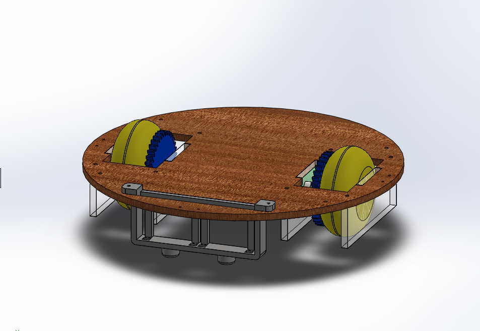
Electrical Design
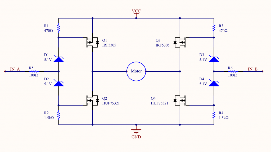
H-Bridges
The Scott Lawson H-Bridge was selected to power the drive train DC motors over the classic H-Bridge design for its reliability and its minimalistic design.
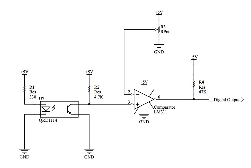
Tape Following
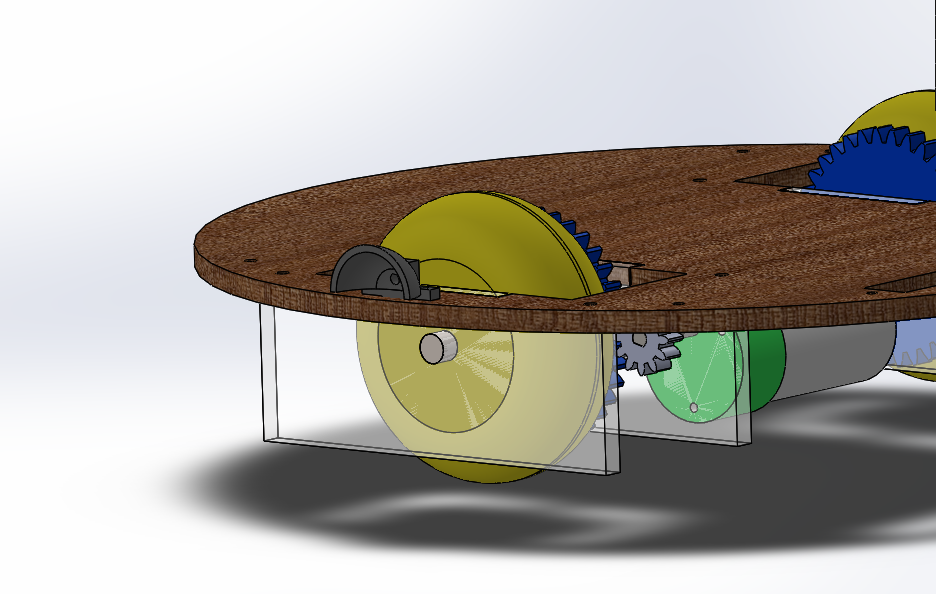
The Roombot was made to follow a track of black electrical tape via digital signals from four QRDs.
In order to isolate the QRD sensor from other sources of light and reflection, black heat shrink was placed around the heat of the QRD to act as as funnel. TODO: bracket positionning
QRD Analog-to-Digital Circuit
The QRD1114 outputs a maximum of 1 mA of current when the surface is reflective. As such, a 4.7kOhm resistor was chosen to scale the output of the QRD to the full 5V range of values.
An Analog-to-Digital Circuit was designed with a modifiable threshold such that the output of the circuit read HIGH when the QRD was on the tape and LOW when the QRD was not.
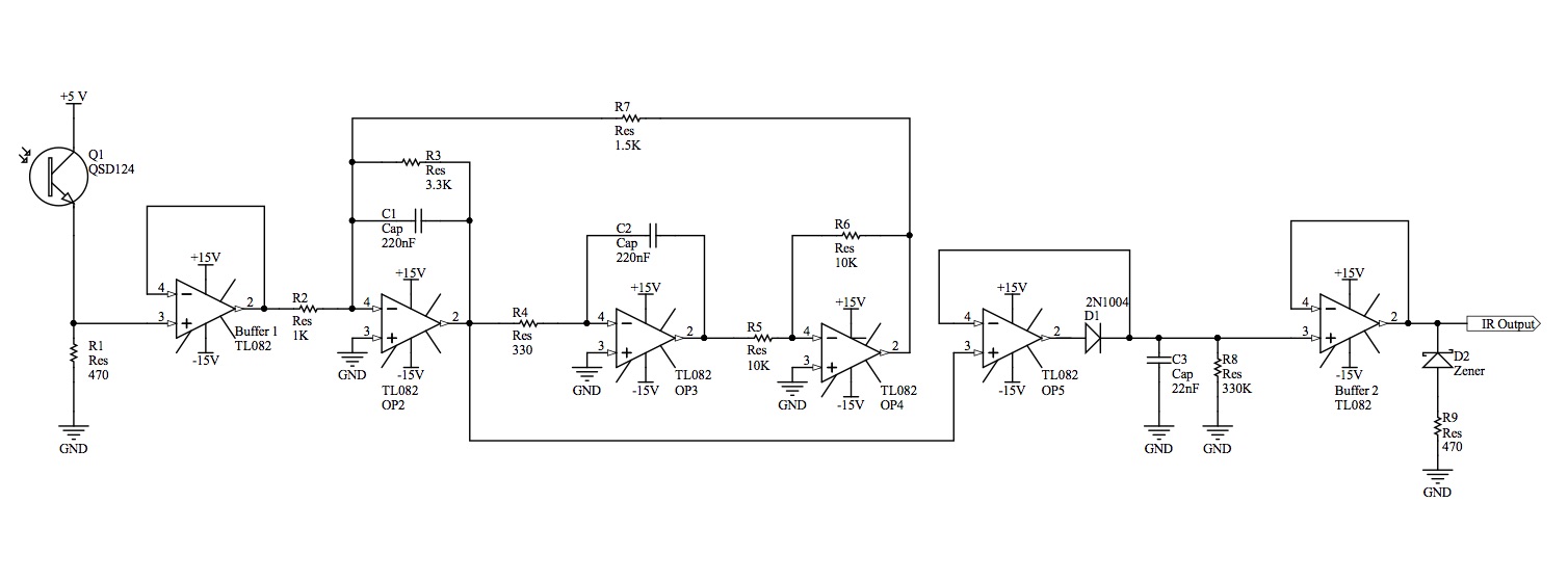
IR Detection
The Roombot was equipped with a total of five QSDs. Three of the QSDs were optimized for passenger detection. Two of the QSDs were optimized for drop-off-zone detection.
QSD Signal Processing Circuit
The QSD Signal Processing Circuit consists of the QSD itself, a Unity Gain Buffer Amplifier, a Biquad Active Filter and finally, a Peak Detector. Resistor and capacitor values were selected to isolate the desired 1kHz frequencies.