Mechanical Design
Overview
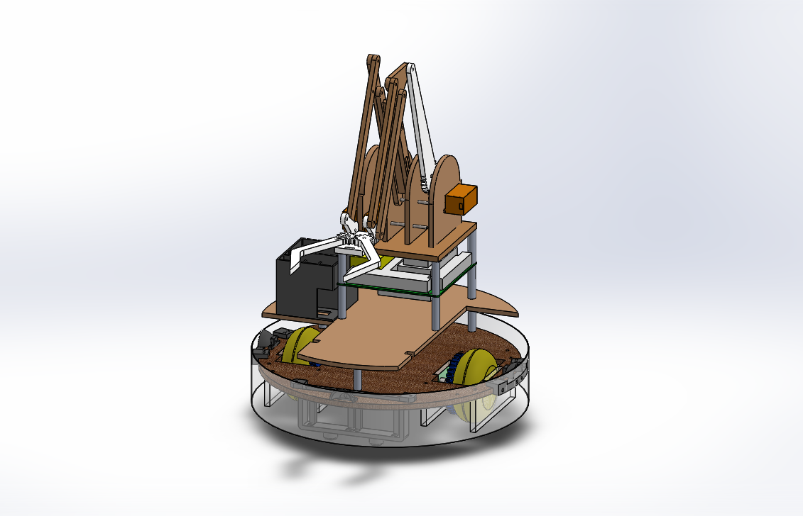
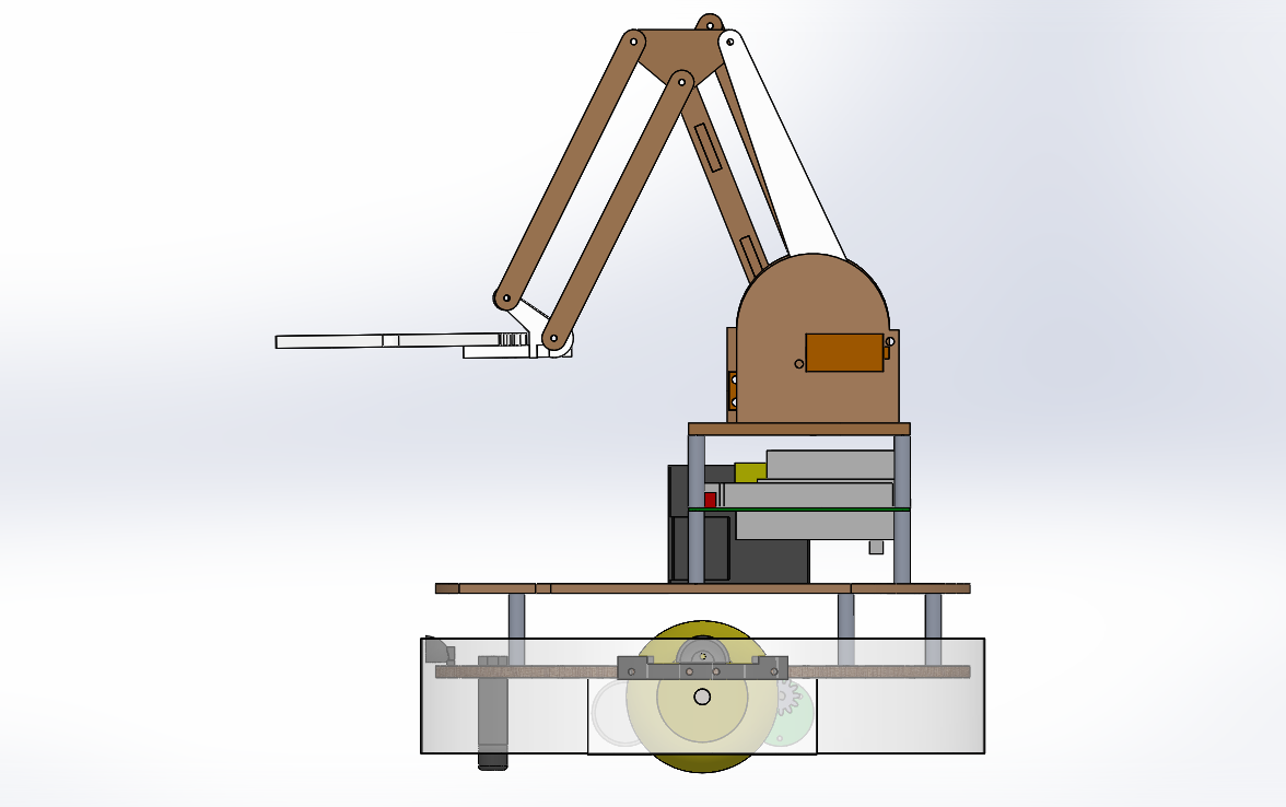
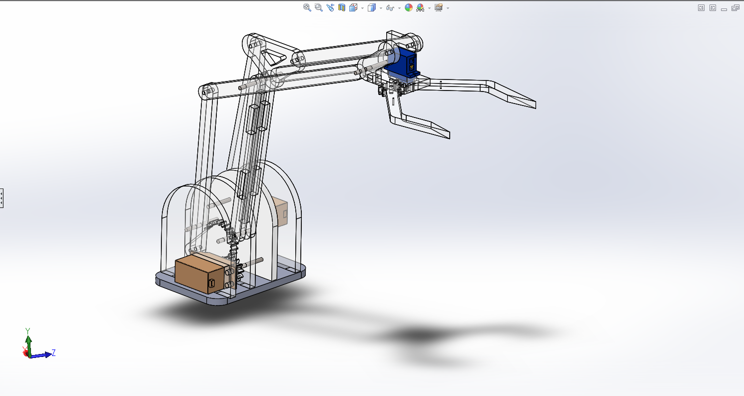
Dimetric and side views of the Roombot (Solidworks).
Chassis
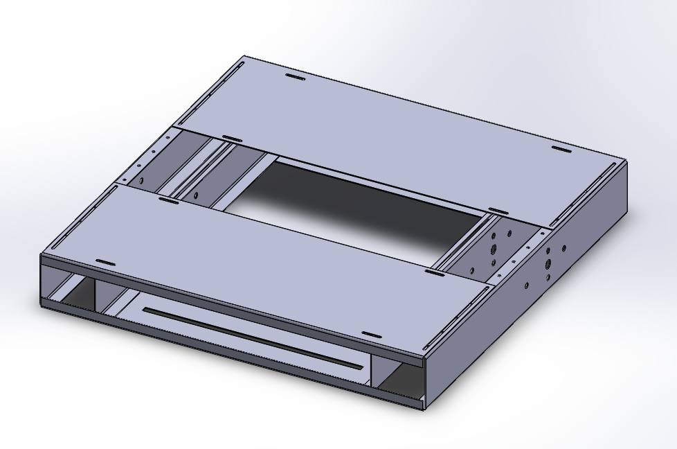
The chassis was the component of the robot with the highest number of redesigns and iterations. The reason for this was because as we built and tested our robot, we found designs that worked as well as designs that didn't work. Despite our redesigns, our final chassis still somewhat resembles our inital design, as shown below.
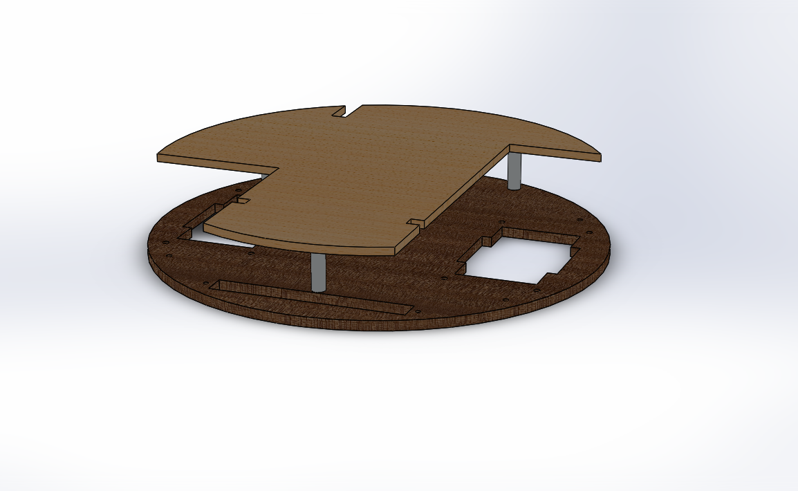
- Versatility and Agility - Every major design choice in the beginning was centered around the robot being able to quickly switch from moving forwards to moving backwards. This meant that our wheels had to be placed in the middle, resulting in a square front/back symmetrical chassis. We later realized that these center wheels could easily be used to turn on the spot, so the chassis was adjusted to be circular to assist this maneuver.
- Strength and Stability - The first chassis unnecessarily durable and strong. This strength came at the price of being complicated, with many separate pieces needing to be assembled. We later realized that the robot only needs to be strong enough to be able to withstand crashes with other robots, thus a single wooden plate would suffice.
- Weight - By reducing the chassis from several sheet metal pieces to a single wooden piece, we greatly decreased the weight of the chassis.
- Ease of Access to Interior - The open design of the original chassis was intended to facilitate easy access to the interior circuits. However we realized that it was extremely difficult and time consuming to change anything that was mechanically attached to the chassis, such as the drive train or the sensors. In the new design, everything is attached to the single plate, making removal and attachment of mechanical parts drastically simpler.
Drivetrain
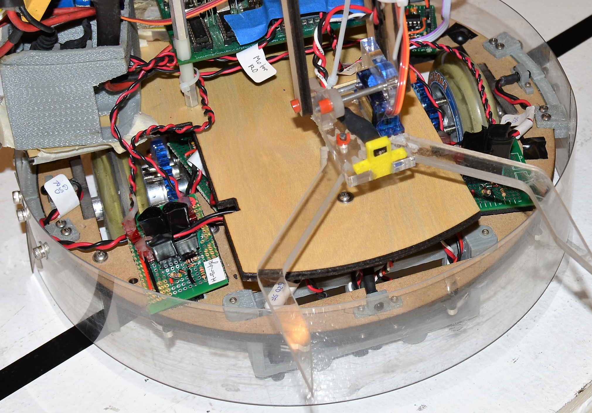
The drive train features two easily removable modules driven by two independent motors, allowing for a large amount of control and flexibility in the robot's movement. Because the drive train was easily removable, the driving gear ratio could easily be calculated and changed to suit the needs of the various design iterations of the rest of the robot. The friction between each rotating piece was reduced by fabricating custom aluminum spacers that would fit on the drive shaft.
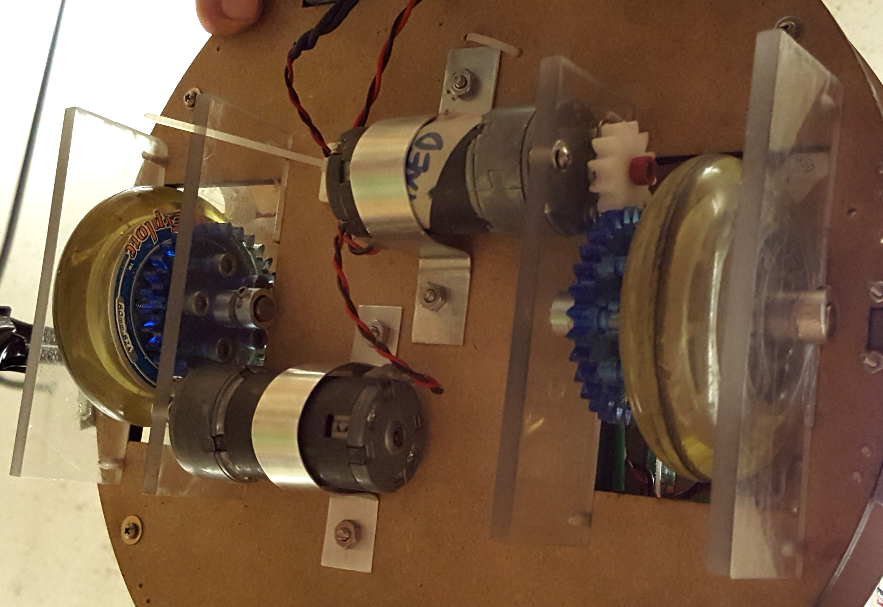
Photograph of the Roombot's drivetrain.
Arm Mechanism
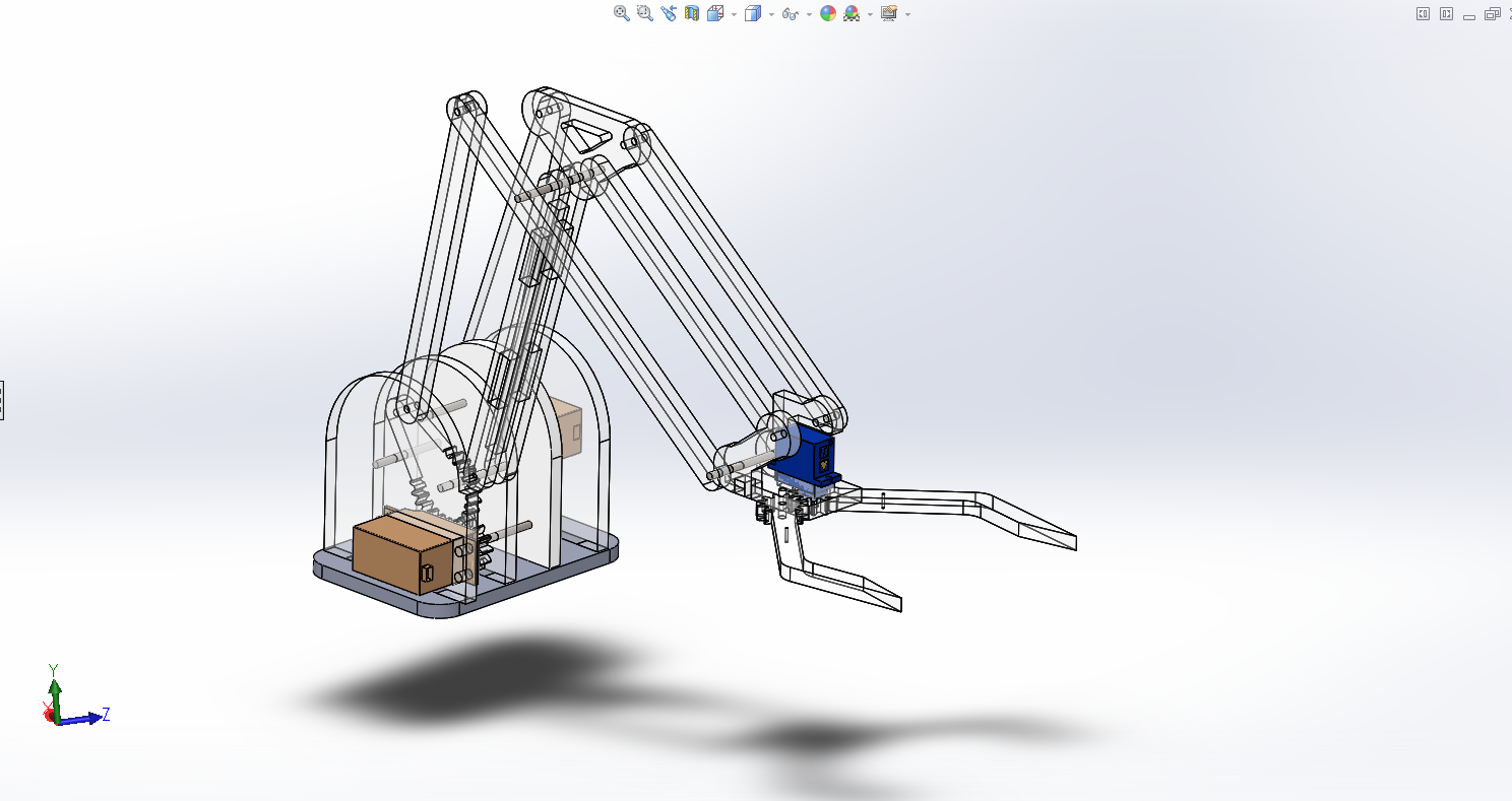
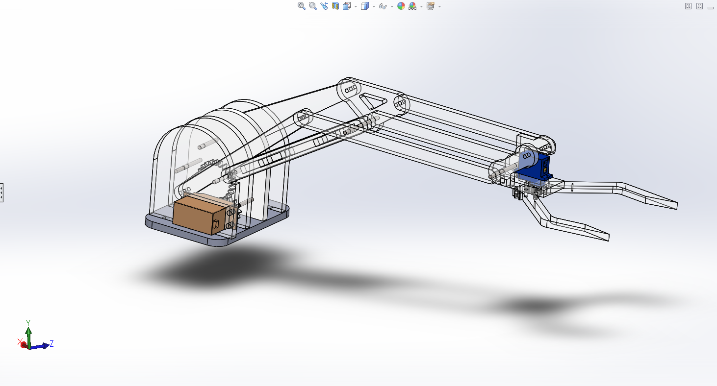
The mechanical arm had a large range and adaptibility, making picking up passengers very consistent. It had two degrees of freedom. The arm could move anywhere within its plane of motion. The arm was actuated by two servo motors at its base, and there is a third servo at the claw. The two servos actuating the motion of the arm work together to bring the claw to any particular point in space. In the gif below, one can see both actuators rotating simulatenously as the arm's position changes.
Arm Stills
Bumper
In order to detect collisions from all sides, we mounted a very flexible circular bumper. The bumper is made of a thin polycarbonate sheet, under which there are a collection of touch sensors. When a robot collides from any side, the bumper is easily depressed, informing the robot to turn around.